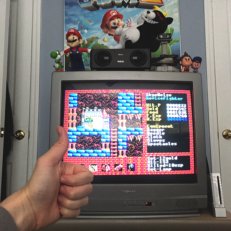
XANADU MSX1 SRAM BATTERY REPACEMENT GUIDE
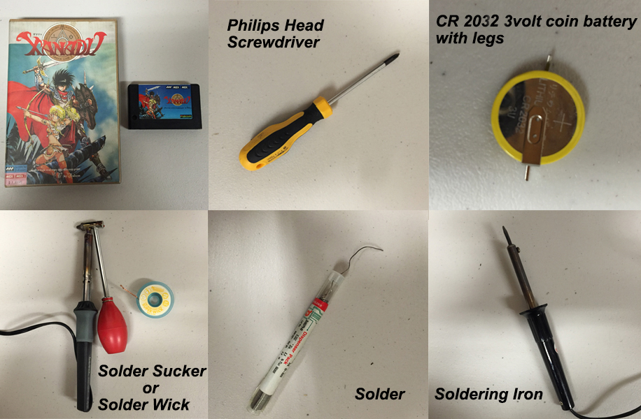
1. Tools you'll need.
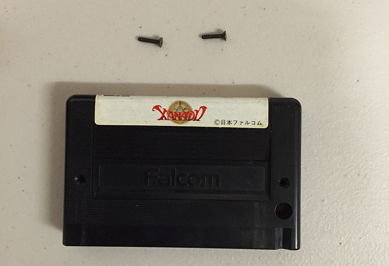
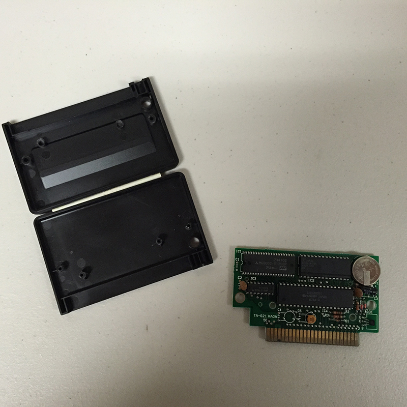
2. Unscrew the two screws on the back of the cartridge.
3. Open the case.
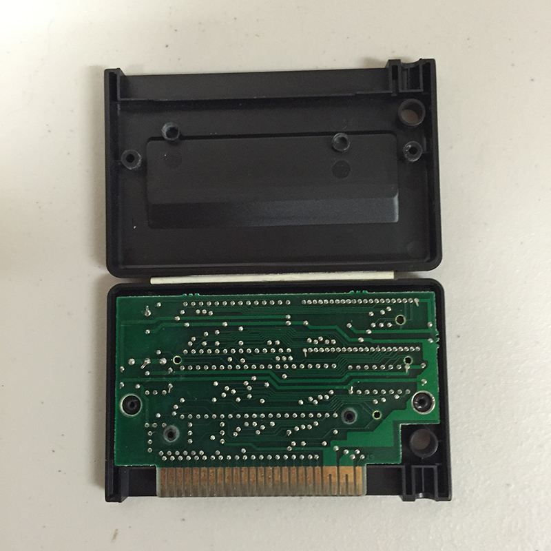
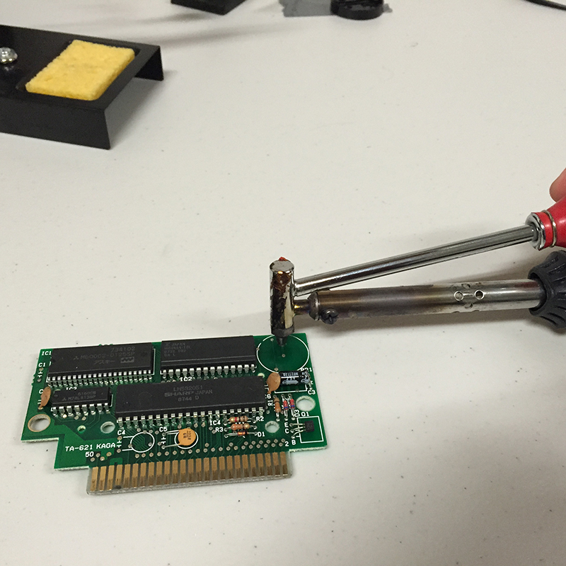
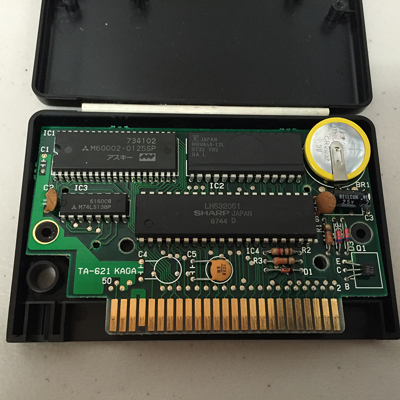
4. Carfully separate the PCB from the case. This can be done by using the screwdriver to carefully pry it up from the side edges taking care not to scratch any nearby traces. If you need more leverage as you pull you can push the screwdriver against the plastic case holes while pulling on the PCB.
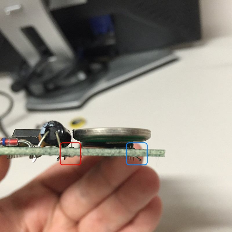
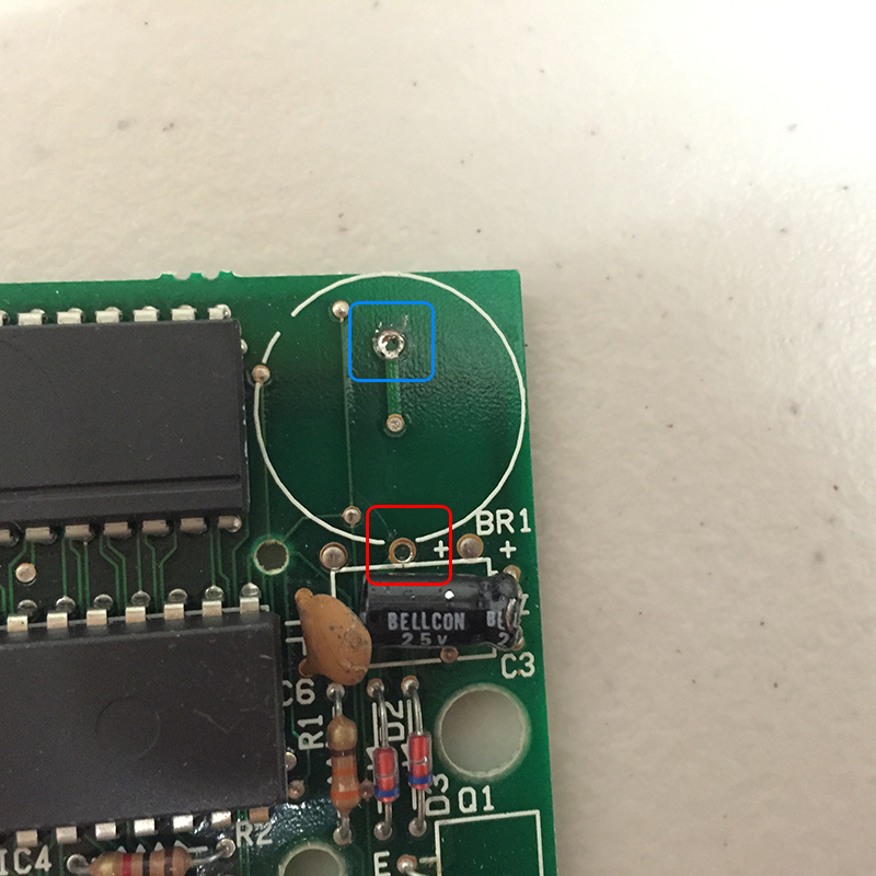
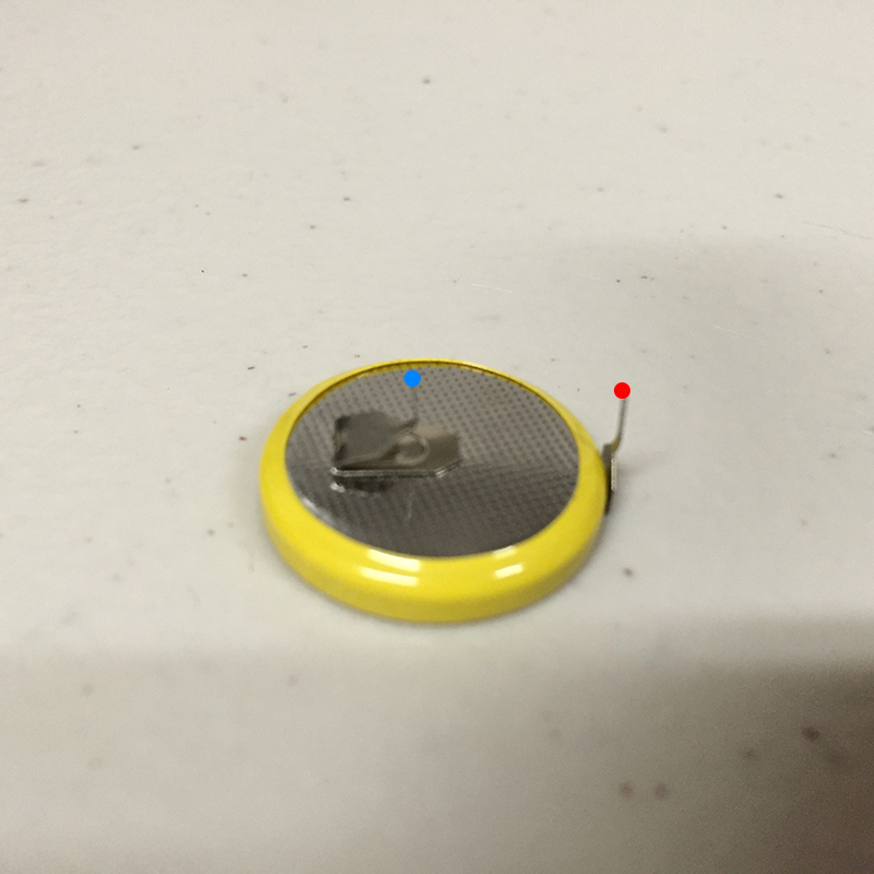
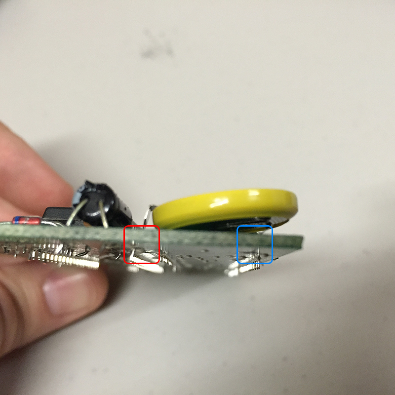
5. This is a side view of the current CR2032 3v coin battery with legs attached to the PCB. Note that the coin battery face up is showing the Postive side.
Red is Postive
Blue is Negative.
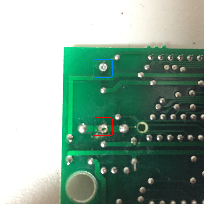
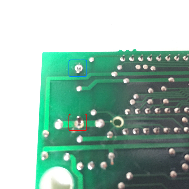
6. Back of the PCB, corresponding solder joints of the CR2032 battery legs.
Red is Postive
Blue is Negative.
*Note* It is best to go ahead and remove the battery now so that it does not act as a heat sink. This can easily be removed by simply rocking the battery from side to side pushing on the left and right sides of it and repeating until the legs snap off allowing you to completely separate the battery from the PCB. There will stil be remnants of the battery legs soldered to the PCB.

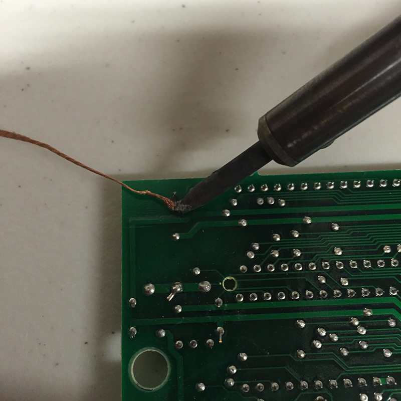
7A. Removal of existing solder around leg, using a soldering iron and solder wick to soak up the old solder.
7B. (Alternative and preferred method) Removal of existing solder around leg, using a solder sucker to suck up the old solder. After sucking up the solder, push the solder out in a disposable container far away from your project as to avoid any fragment solder pieces getting onto the PCB.
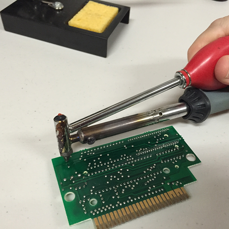
7C. Removal of existing solder around leg, using a solder sucker to suck up the old solder. This time on the Front side.
Repeat this step on either side as needed for both solder joints for Postive and Negative and remove legs.
8. Top of PCB, with Solder and Legs removed. Open holes are what you want to have for inserting the new battery legs.
9. Bottom of PCB, with Solder and Legs removed. Open holes are what you want to have for inserting the new battery legs.
10. How I decided to bend the CR2032 battery legs to best fit the placement of the holes on the PCB. Notice that the Blue leg is bent inward and then down, while Red is simply bent down.
11. Side view with placement of new battery with Postive side facing up.
Red leg is Postive
Blue leg is Negative.
12. Top view with placement of new battery with Postive side facing up.
13. Bottom view with placement of new battery inserted. I recommned bending the legs inward to help keep the legs tightly positioned before soldering.
Red is Postive
Blue is Negative.
14. Top view with placement of new battery with Postive side facing up and inserted back into case.
15. Close case up with screws.
16. Enjoy! (CTRL+ Q for Save to SRAM (costs 100 Gold each time) and CTRL+R for Restore from SRAM)